274 Results
View results:
Sort by:
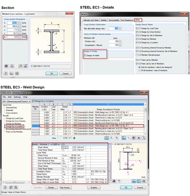
When using a welded profile, weld seam verification can also be carried out in RF-/STEEL EC3 as part of the design. The program performs the typical designs according to EN 1993‑1‑8.
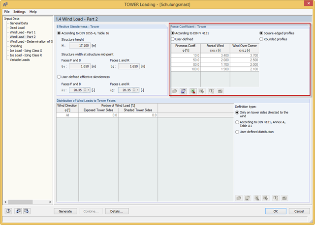
RF-/TOWER load was extended with force coefficients for rounded profiles of four-sided towers and square-edged profiles of three-sided towers. The force coefficients for rounded profiles are determined using the Reynolds number. Previously, you could only use the rounded profiles for four‑sided towers and the square‑edged profiles for three‑sided towers.
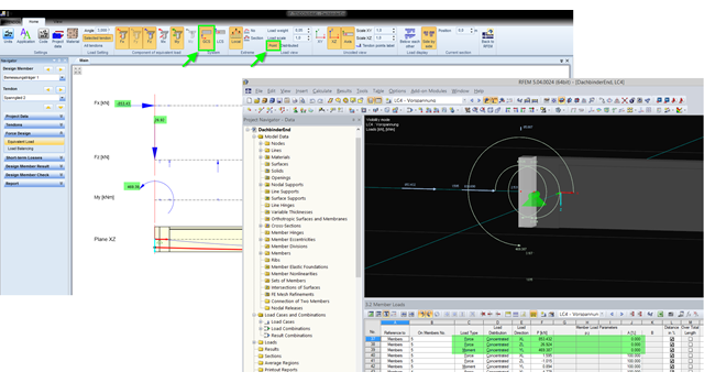
The equivalent loads determined in RF-TENDON due to prestress are transferred in RFEM as member loads or as line loads. A member load is used for member types with their own stiffness; a line load is used for member types without their own stiffness. In order to understand which values of the concentrated loads are to be transferred from RF‑TENDON to RFEM, you should use the following display settings: ~ Reference of the loads to the global coordinate system (GCS), ~ Load display: "Point"
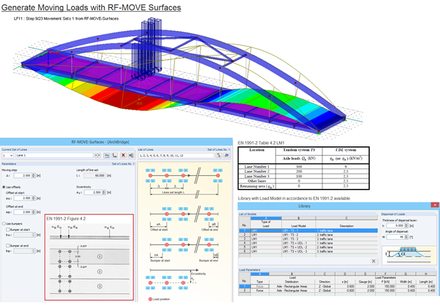
Moving loads can be generated easily with RF‑MOVE Surfaces. A library is available with load models as defined in Eurocode 1, Part 2. The input of step size, offsets at start and end, and the distance to a reference line make it possible for the user to generate user‑defined load models and influence the number of load cases generated. RF‑MOVE Surfaces generates load cases and, optionally, a result combination as an envelope of all results.
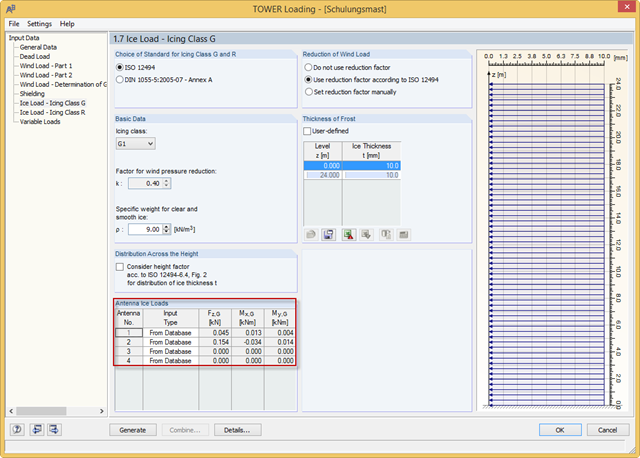
With the RFEM 5.04.0024 and RSTAB 8.04.0024 versions, you can define the antenna ice loads in RF‑/TOWER Loading. The program provides the values from the manufacturer databases. In addition, you can define the ice loads manually or use the calculation based on simplified geometry.

Diagonals of double angles are used for pipe bridge construction and for truss girders, among other things. They are usually subjected to tension, but it is necessary to transfer them in smaller compression forces with regard to the load application. In the case of slender diagonals in particular, you should also consider the bending due to self‑weight.

The new RF‑/DYNAM Pro - Natural Vibrations module has been available since RFEM version 5.04.xx and RSTAB version 8.04.xx were released. Masses can now be imported directly from load cases and load combinations.
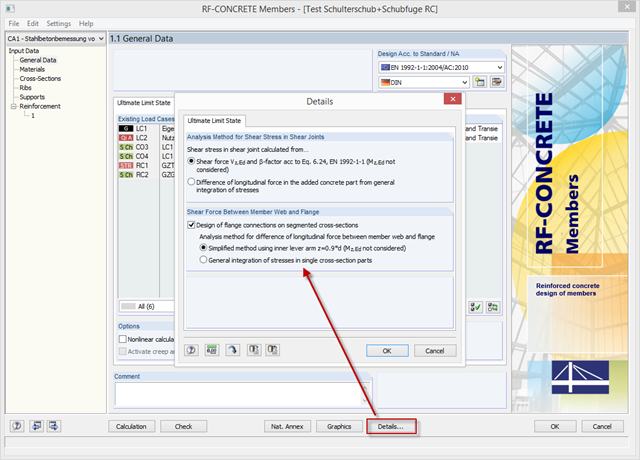
With the latest version of CONCRETE and RF-CONCRETE Members, it is possible to perform shear design for the connection of compression and tension flanges on a T-beam web.
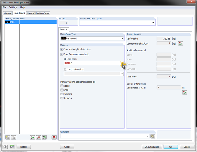
In RF-/DYNAM Pro - Natural Vibrations, it is possible to transfer complete load cases/load combinations as masses. To do this, you can simply save the load case or the load combination to be considered as a mass case in the add‑on module.
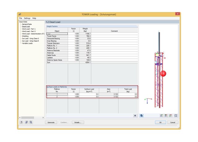
In the RFEM 5.04.0024 and RSTAB 8.04.0024 versions, there is a new feature in RF‑/TOWER Loading that allows you to define additional surface loads in a load case for dead loads; for example, from grids on platforms.

A previous article describes the design of double angles. It deals with analysis performed on a single member.
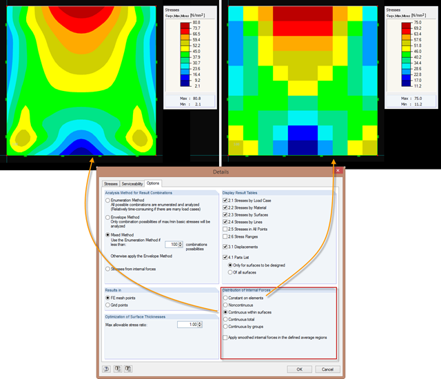
Just as in the RFEM Display Navigator, you can set the distribution of internal forces in surfaces in RF‑STEEL Surfaces. Since deformations are always the result of the FEM calculation, the corresponding forces will be recalculated. This means that the internal forces on an FEM element are calculated depending on the composition (triangular or square) in three or four places. In order to obtain continuous internal forces and thus a smoothed distribution, these internal forces have to be interpolated. Interpolation is done by selecting the "Distribution of internal forces" option in the surfaces.
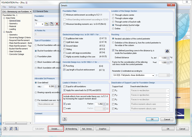
In RFEM and RSTAB, the internal forces of individual load combinations are determined according to the second-order analysis by default. If you use the RF‑CONCRETE add‑on module for stability analysis of reinforced concrete columns, you can change the calculation method of LCs to the linear static analysis, since the effects of the second‑order analysis are already considered in the calculation according to the model column method in RF‑CONCRETE Columns (nominal curvature method).
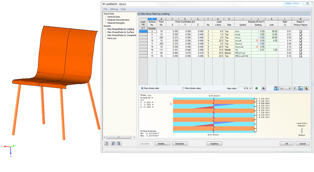
In RF‑LAMINATE, you can also design curved quadrangle surfaces. In the example in the figure, the cross-laminated timber layers of a chair are designed.
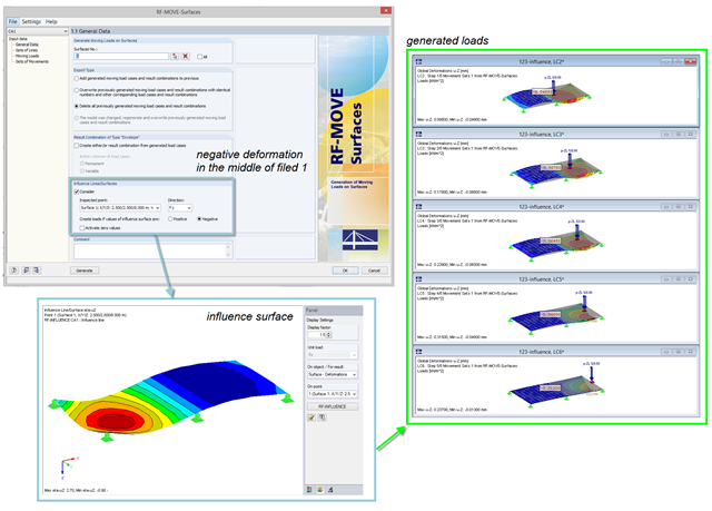
For the reduction of loads generated in RF‑MOVE Surfaces, you can consider the influence surfaces of a selected point. The influence surfaces are determined by RF-INFLUENCE. This procedure is useful in cases where only unfavorably acting loads should be considered. Depending on the unfavorable action, you should select the positive or negative direction.
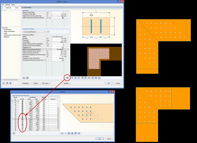
In RF‑/JOINTS Timber, you can remove an individual dowel from the calculation, thus creating any dowel layout. The calculation disregards these removed dowels for the ultimate limit state design, as well as for the net timber cross‑section analysis and the rotational spring stiffness determination.
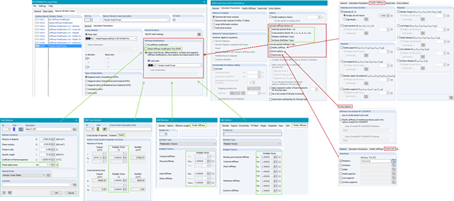
In RF-/DYNAM Pro - Natural Vibrations, you can import axial forces and stiffness modifications from any Load Case (LC) or Load Combination (CO). You can modify material, cross‑section, member, and surface properties and activate these modifications in the LC/CO calculation parameters.

In order to design longitudinal reinforcement for the serviceability limit state, it is necessary to enable this function. This is possible in Window 1.1 General Data under the "Serviceability Limit State" tab. After you select the "Analytical..." method of checking, you can select the corresponding additional options in the section for determining the longitudinal reinforcement of the "Settings of Analytical Method of Serviceability Limit State Design" window.
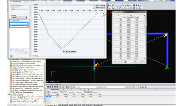
RF-/DYNAM Pro - Forced Vibrations provides the option of a time course monitor. During the evaluation process, you can compare several graphs directly in the program. In addition, you can transfer the figures to the printout report or export them directly to Excel as a value table.
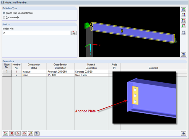
In RF-/JOINTS Steel - Pinned, it is possible to design connections without a supporting structure (for example, columns). In this case, the beam is connected to an anchor plate. How is this kind of connection defined?